Laboratory 3 - Theory
Arithmetic instructions
ADC
Syntax:
adc <regd>,<regs>; <regd> ← <regd> + <regs> + CF
adc <reg>,<mem>; <reg> ← <reg> + <mem> + CF
adc <mem>,<reg>; <mem> ← <mem> + <reg> + CF
adc <reg>,<con>; <reg> ← <reg> + <con> + CF
adc <mem>,<con>; <mem> ← <mem> + <con> + CF
Semantics and restrictions:
- The value of the carry flag (CF) is added to the sum of the two operands
- Both operands should have the same type: byte, word or doubleword.
- While both operand can be registers, at most one operand can be a memory location.
Example:
adc EDX,EBX; EDX ← EDX + EBX + CF
adc AX,[var]; AX ← AX + [var] + CF
adc [var],AX; [var] ← [var] + AX + CF
adc EAX,123456h; EAX ← EAX + 123456h + CF
adc BYTE [var],10; BYTE [var] ← BYTE [var] + 10 + CF
SBB
Syntax:
sbb <regd>,<regs>; <regd> ← <regd> - <regs> - CF
sbb <reg>,<mem>; <reg> ← <reg> - <mem> - CF
sbb <mem>,<reg>; <mem> ← <mem> - <reg> - CF
sbb <reg>,<con>; <reg> ← <reg> - <con> - CF
sbb <mem>,<con>; <mem> ← <mem> - <con> - CF
Semantics and restrictions:
- The value of the carry flag (CF) is substracted from (dest - source)
- Both operands should have the same type: byte, word or doubleword.
- While both operand can be registers, at most one operand can be a memory location.
Example:
sbb EDX,EBX; EDX ← EDX - EBX - CF
sbb AX,[var]; AX ← AX - [var] - CF
sbb [var],AX; [var] ← [var] - AX - CF
sbb EAX,123456h; EAX ← EAX - 123456h - CF
sbb byte [var],10; BYTE [var] ← BYTE [var] - 10 - CF
IMUL
Syntax:
imul <op8>; AX ← AL * <op8>
imul <op16>; DX:AX ← AX * <op16>
imul <op32>; EDX:EAX ← EAX * <op32>
Semantics and restrictions:
- The result of the multiplication operation is stored on double the size of the operands.
- IMUL instruction performs the multiplication operation for signed integers.
- The first operand and the result are stored in registers.
- Although the operation is binary, only one operand is specified, while the second operand and the location of the result are fixed.
- The explicit operand can be a register or a variable, but it cannot be an immediate value (a constant).
Example:
imul DH; AX ← AL * DH
imul mem8; AX ← AL * mem8
imul DX; DX:AX ← AX * DX
imul EBX; EDX:EAX ← EAX * EBX
IDIV
Syntax:
idiv <reg8>; AL ← AX / <reg8>, AH ← AX % <reg8>
idiv <reg16>; AX ← DX:AX / <reg16>, DX ← DX:AX % <reg16>
idiv <reg32>; EAX ← EDX:EAX / <reg32>, EDX ← EDX:EAX % <reg32>
idiv <mem8>; AL ← AX / <mem8>, AH ← AX % <mem8>
idiv <mem16>; AX ← DX:AX / <mem16>, DX ← DX:AX % <mem16>
idiv <mem32>; EAX ← EDX:EAX / <mem32>, EDX ← EDX:EAX % <mem32>
Semantics and restrictions:
- IDIV instruction performs the division operation for signed integers.
- The first operand and the result are stored in registers.
- The first operand is not explicitly specified and it has double the size of the second operand.
- The explicit operand can be a register or a variable, but it cannot be an immediate value (a constant).
- Dividing a large number by a small number, it is possible that the result exceeds the capacity of representation. In this case the same error is triggered as in the case of a division by 0.
Example:
idiv CL; AL ← AX / CL, AH ← AX % CL
idiv SI; AX ← DX:AX / SI, DX ← DX:AX % SI
idiv EBX; EAX ← EDX:EAX / EBX, EDX ← EDX:EAX % EBX
idiv DWORD [var]; EAX ← EDX:EAX / DWORD [var], EDX ← EDX:EAX % DWORD [var]
Signed conversion instructions
CBW
Syntax:
cbw
Semantics and restrictions:
- Converts the byte AL to the word AX in the signed interpretation
- The conversion refers to the extension of the representation from 8 bits to 16 bits, by filling AH with the sign bit of AL.
- The instruction does not have any explicitly specified operands because it is always converting AL → AX.
Example:
cbw ; if AL=01110111b then AX ← 00000000 01110111b
    ; if AL=11110111b then AX ← 11111111 11110111b
CWD
Syntax:
cwd
Semantics and restrictions:
- Converts the word AX to the doubleword DX:AX in the signed interpretation.
- The conversion refers to the extension of the representation from 16 bits to 32 bits, by filling DX with the sign bit of AX.
- The instruction does not have any explicitly specified operands because it is always converting AX → DX:AX.
Example:
cwd ; if AX=00110011 11001100b then DX:AX ← 00000000 00000000 00110011 11001100b
    ; if AX=10110011 11001100b then DX:AX ← 11111111 11111111 10110011 11001100b
CWDE
Syntax:
cwde
Semantics and restrictions:
- Converts the word AX to the doubleword EAX in the signed interpretation.
- The conversion refers to the extension of the representation from 16 bits to 32 bits, by filling the high word of EAX with the sign bit of AX.
- The instruction does not have any explicitly specified operands because it is always converting AX → EAX.
Example:
cwde ; if AX=00110011 11001100b then EAX ← 00000000 00000000 00110011 11001100b
     ; if AX=10110011 11001100b then EAX ← 11111111 11111111 10110011 11001100b
CDQ
Syntax:
cdq
Semantics and restrictions:
- Converts the doubleword EAX to the qword EDX:EAX in the signed interpretation.
- The conversion refers to the extension of the representation from 32 bits to 64 bits, by filling EDX (the high doubleword) with the sign bit of EAX.
- The instruction does not have any explicitly specified operands because it is always converting EAX → EDX:EAX.
Example:
cdq ; if EAX=00110011 11001100 00110011 11001100b then EDX:EAX ← 00000000 00000000 00000000 00000000 00110011 11001100 00110011 11001100b
     ; if EAX=10110011 11001100 10110011 11001100b then EDX:EAX ← 11111111 11111111 11111111 11111111 10110011 11001100 10110011 11001100b
Unsigned conversions
Unsigned conversions
- There are no instructions for conversions in the unsigned representation!
- In assembly language, the unsigned conversions are done by putting 0 in the high byte, word or doubleword:
Example
mov AH,0 ; for converting AL → AX
mov DX,0 ; for converting AX → DX:AX
mov EDX,0 ; for converting EAX → EDX:EAX
Declaring variables / constants
Declaring variables with initial value
a DB 0A2h ;declaring the variable a of type BYTE and initialising it with the value 0A2h
b DW 'ab' ;declaring the variable a of type WORD and initialising it with the value 'ab'
c DD 12345678h ;declaring the variable a of type DOUBLE WORD and initialising it with the value 12345678h
d DQ 1122334455667788h ;declaring the variable a of type QUAD WORD and initialising it with the value 1122334455667788h
Declaring variables without initial value
a RESB 1 ;reserving 1 byte
b RESB 64 ;reserving 64 bytes
c RESW 1 ;reserving 1 word
Defining constants
ten EQU 10 ;defining the constant ten that has the value 10
Notations
<op8>    - operand on 8 bits
<op16>   - operand on 16 bits
<op32>   - operand on 32 bits

<reg8>   - register on 8 bits
<reg16>  - register on 16 bits
<reg32>  - register on 32 bits
<reg>    - register
<regd>   - destination register
<regs>   - source register

<mem8>   - memory variable on 8 bits
<mem16>  - memory variable on 16 bits
<mem32>  - memory variable on 32 bits
<mem>    - memory variable

<con8>   - constant (immediate value) on 8 bits
<con16>  - constant (immediate value) on 16 bits
<con32>  - constant (immediate value) on 32 bits
<con>    - constant (immediate value)
Little endian representation
Theory
- Each byte has an address (the byte being the smallest addressable unit of memory)
- An address identifies in a unique way a location in memory, and x86 processors assign each byte location a separate memory address
- x86 processors store and retrieve data from memory using little endian order (the byte representing the „end” of the number will be stored at the „little”-est address):
- The least significant byte is stored at the beginning of that memory area (at the address where allocation for the data begins).
- The remaining bytes are stored in reverse order in the next consecutive memory positions.
(much more clearer as an informal statement: if we have on paper or in a register a 4 bytes number and we denote the order of these bytes as 1 2 3 4 , in the memory the little-endian representation will store that number in the reverse order of its bytes: 4 3 2 1).
Careful ! – only the BYTES order is reversed in memory, NOT the BITS inside that bytes !!!!! The order of the bits which compose each byte remains the same !
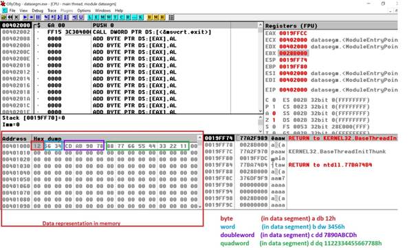
For instance, if we have the following data segment:
a db 12h
b dw 3456h
c dd 7890abcdh
d dq 1122334455667788h
Data representation in memory will be as shown in the lowest left corner from the below debugger configuration:
Example 1: Addition: quadword+quadword
bits 32 ;assembling for the 32 bits architecture
; the start label will be the entry point in the program
global start
extern exit ; we inform the assembler that the exit symbol is foreign, i.e. it exists even if we won't be defining it
import exit msvcrt.dll; exit is a function that ends the process, it is defined in msvcrt.dll
; msvcrt.dll contains exit, printf and all the other important C-runtime functions
segment data use32 class=data ; the data segment where the variables are declared
a dq 1122334455667788h
b dq 0abcdef1a2b3c4d5eh
r resq 1 ; reserve 1 quadword in memory to save the result
; our code starts here
segment code use32 class=code ; code segment
start:
;11223344 55667788 h -> EDX : EAX
; EDX : EAX
mov eax, dword [a+0]
mov edx, dword [a+4]
; abcdef1a 2b3c4d5e h -> ECX : EBX
; ECX : EBX
mov ebx, dword [b+0]
mov ecx, dword [b+4]
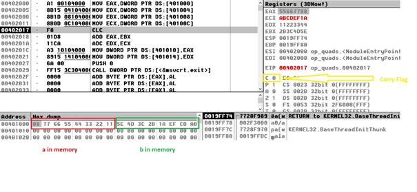
;a + b
; edx : eax +
; ecx : ebx
clc ; clear Carry Flag (punem 0 in CF)
add eax, ebx ; eax= eax+ebx
adc edx, ecx ; edx = edx+ecx + CF
;(CF is set is add eax, ebx produce a carry)
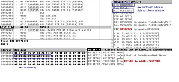
;edx:eax -> r
mov dword [r+0], eax
mov dword [r+4], edx
push dword 0 ; push the parameter for exit onto the stack
call [exit] ; call exit to terminate the programStep 1 – before perform the addition
Example 2. Division: quadword/doubleword
bits 32 ;assembling for the 32 bits architecture
; the start label will be the entry point in the program
global  start

extern  exit ; we inform the assembler that the exit symbol is foreign, i.e. it exists even if we won't be defining it

import  exit msvcrt.dll; exit is a function that ends the process, it is defined in msvcrt.dll
        ; msvcrt.dll contains exit, printf and all the other important C-runtime functions
segment  data use32 class=data ; the data segment where the variables are declared
	m dq 1122334455667788h
	n  dd 0ccddeeddh
	rezd  resd 1
	; our code starts here
segment  code use32 class=code ; code segment
start:
	mov  ebx, [n]

	;11223344  55667788 h -> EDX : EAX
	;   EDX   :   EAX
	mov eax, dword [m+0]
	mov edx, dword [m+4]

	div ebx ; edx:eax/ebx=eax cat si edx rest

	mov dword[rezd], eax

	push  dword 0  ; push  the parameter for exit onto the stack
	call  [exit] ; call exit to terminate the program
Stack in assembly
Theory
- The runtime stack is a memory array managed directly by the CPU, using the ESP register, known as the stack pointer register.
- The ESP register holds a 32-bit offset into some location on the stack. We rarely manipulate ESP directly; instead, it is indirectly modified by instructions such as CALL, RET, PUSH, and POP.
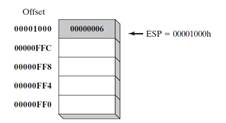
- ESP always points to the last value to be added to, or pushed on, the top of stack.
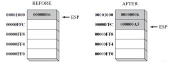
- In Figure 1, the ESP (extended stack pointer) contains hexadecimal 00001000, the offset of the most recently pushed value (00000006).
- In our diagrams, the top of the stack moves downward when the stack pointer decreases in value:
- Each stack location in this figure contains 32 bits, which is the case when a program is running in 32-bit mode. In 16-bit real-address mode, the SP register points to the most recently pushed value and stack entries are typically 16 bits long.
PUSH Operation
- A 32-bit push operation decrements the stack pointer by 4 and copies a value into the location in the stack pointed to by the stack pointer.
- Figure 2 shows the effect of pushing 000000A5 on a stack that already contains one value (00000006). Notice that the ESP register always points to the top of the stack.
- The figure shows the stack ordering opposite to that of the stack of plates we saw earlier, because the runtime stack grows downward in memory, from higher addresses to lower addresses. Before the push, ESP = 00001000h; after the push, ESP = 00000FFCh.
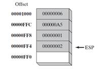
- Figure 3 shows the same stack after pushing a total of four integers.
POP Operation
- A pop operation removes a value from the stack. After the value is popped from the stack, the stack pointer is incremented (by the stack element size) to point to the next-highest location in the stack.
- Figure 4 shows the stack before and after the value 00000002 is popped.
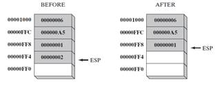
- The area of the stack below ESP is logically empty, and will be overwritten the next time the current program executes any instruction that pushes a value on the stack.
Stack Applications
- A stack makes a convenient temporary save area for registers when they are used for more than one purpose. After they are modified, they can be restored to their original values.
- When the CALL instruction executes, the CPU saves the current subroutine’s return address on the stack.
- When calling a subroutine, you pass input values called arguments by pushing them on the stack.
- The stack provides temporary storage for local variables inside subroutines.
PUSH and POP Instructions
PUSH Instructions
The PUSH instruction first decrements ESP and then copies a source operand into the stack.A 16-bit operand causes ESP to be decremented by 2. A 32-bit operand causes ESP to be decremented by 4. There are three instruction formats:
PUSH reg/mem16
PUSH reg/mem32
PUSH imm32
POP Instructions
The POP instruction first copies the contents of the stack element pointed to by ESP into a 16- or 32-bit destination operand and then increments ESP. If the operand is 16 bits, ESP is incremented by 2; if the operand is 32 bits, ESP is incremented by 4:POP reg/mem16
POP reg/mem32PUSHFD and POPFD Instructions
- The PUSHFD instruction pushes the 32-bit EFLAGS register on the stack, and POPFD pops the stack into EFLAGS:
pushfd
popfd- 16-bit programs use the PUSHF instruction to push the 16-bit FLAGS register on the stack and POPF to pop the stack into FLAGS.
- in 32 bits programming both PUSHF and PUSHFD can be used in order to push the 32-bit EFLAGS on the stack
- The MOV instruction cannot be used to copy the flags to a variable, so PUSHFD may be the best way to save the flags. There are times when it is useful to make a backup copy of the flags so you can restore them to their former values later. Often, we enclose a block of code within PUSHFD and POPFD:
pushfd ; save the flags
;
; any sequence of  statements here...
;
popfd ; restore the flags- When using pushes and pops of this type, be sure the program’s execution path does not skip over the POPFD instruction. When a program is modified over time, it can be tricky to remember where all the pushes and pops are located.
The need for precise documentation is critical!
A less error-prone way to save and restore the flags is to push them on the stack and immediately pop them into a variable:
.data
saveFlags DW 0
.code
pushfd ; push flags on  stack
pop saveFlags ; copy into a variable- The following statements restore the flags from the same variable:
push saveFlags ; push  saved flag values
popfd ; copy into the  flags
PUSHAD, PUSHA, POPAD, and POPA
- The PUSHAD instruction pushes all of the 32-bit general-purpose registers on the stack in the following order:
EAX, ECX, EDX, EBX, ESP (value before executing PUSHAD), EBP, ESI, and EDI. - The POPAD instruction pops the same registers off the stack in reverse order.
- Similarly, in 16 bits programs the PUSHA instruction, introduced with the 80286 processor, pushes the 16-bit generalpurpose registers (AX, CX, DX, BX, SP, BP, SI, DI) on the stack in the order listed.
- The POPA instruction pops the same registers in reverse order.
- in 32 bits programming POPA and POPAD, respectively PUSHA and PUSHAD have the same behavior
If you write a procedure that modifies a number of 32-bit registers, use PUSHAD at the beginning of the procedure and POPAD at the end to save and restore the registers. The following code fragment is an example:
pushad ; save  general-purpose registers
.
.
mov eax,...
mov edx,...
mov ecx,...
.
.
popad ; restore general-purpose registers- An important exception to the foregoing example must be pointed out; procedures returning results in one or more registers should not use PUSHA and PUSHAD.
- Suppose the following ReadValue procedure returns an integer in EAX; the call to POPAD overwrites the return value from EAX:
ReadValue PROC
pushad ; save  general-purpose registers
.
.
mov eax,return_value
.
.
popad ; overwrites EAX!
ret
ReadValue ENDP
Examples
- Unlike the ESP register, the base pointer EBP is manipulated only explicitly.
- EBP is used by high-level languages to reference function parameters and local variables on the stack. It should not be used for ordinary arithmetic or data transfer except at an advanced level of programming. It is often called the extended frame pointer register.
- EBP role will be clarified in the last courses of the semester when the integration of Assembly Language with high level programming languages (namely C in our case) will be studied. But, a few words on the role of the EBP and ESP stack registers in the functioning of the run time stack can be said at this moment also, considering only an ASM code to implement a function, concept recognized only by a high-level programming language.
- A new procedure/function that is called will become the currently executing subroutine, so in the run time stack a new stackframe must be built for this subroutine. This new stackframe will be delimited by the EBP (at the basis) and the ESP (at the top) stack pointer registers, so the values from EBP and ESP must be updated for adapting to the new subroutine context.
- But, for being able after the call to return to the caller, the caller’s stackframe must be restored, so the current (”old”) EBP value for the caller has to be saved. This is done as the first thing by the new called subroutine, which saves IN THE STACK using a PUSH EBP the base address of the caller’s stackframe. After that, the EBP value can be updated to point to the beginning of the new stackframe (mov ebp,esp), which will be exactly the location shown by ESP, so the new stackframe will start with the value of the „old” EBP. So, in this point EBP and ESP have both the same value (indicating that the new stackframe is empty and ready to receive the required data to „grow” and start the execution of the current subroutine.
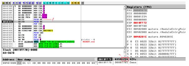
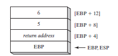
- This mechanism is briefly illustrated below in the case of a procedure called AddTwo which will add the values of the two passed parameters and returns their sum in EAX:
AddTwo:
push ebp; saving the caller’s stackframe base for further being able to restore it
mov ebp,esp ; initialising the base of the new stack frame for the currently executing
; procedure AddTwo (see the picture below which illustrates exactly
; this described situation)
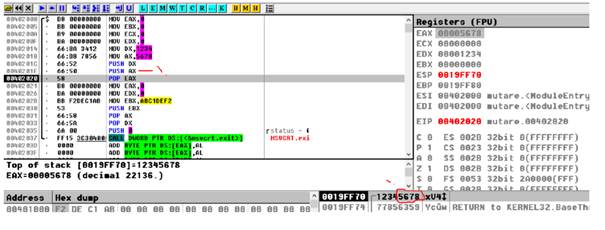
mov eax,[ebp + 12] ; transferring into EAX the value of the second parameter passed
; on to the stack by the caller BEFORE the new stackframe takes
; the run time control
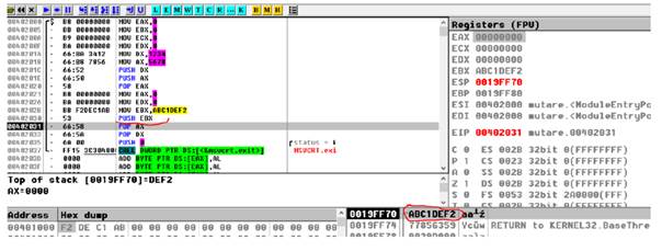
add eax,[ebp + 8] ; adding to EAX the first parameter
pop ebp ; restoring the caller stackframe as being the new currently executing one
ret ; going back immediately to the point of call for continuing the execution
; of the program
Stack Frame after Pushing EBP and ESP value was copied to EBP:
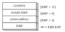
After the next two instructions (mov and add) execute, the following figure shows the contents of the stack frame: a function call such as AddTwo(5, 6) would cause the second parameter to be pushed on the stack, followed by the first parameter:
AddTwo could push additional registers on the stack without altering the offsets of the stack parameters from EBP. ESP would change value, but EBP would not.